Wednesday, August 20, 2014

New Servo Follower Valves                                                        

New servo follower valve
I made new servo follower valves and installed them on the legs. The holes in these valves are of a narrow triangular shape, such that as the leg is nearing it’s target position the flow of air in or out of the piston cylinder is restricted. The slower movement minimizes the overshoot oscillation motion which was giving me a problem.


The video shows a leg test where the legs take turns going up and down rather slowly. There are still occasional sudden unexpected movements that are worrisome, but I think I will go ahead with the programming of the legs and cart just to see what will happen.


Saturday, August 16, 2014

Leg Harmonic Motion Problem                                               


I attached the legs to the cart thinking that when the legs were compressed by the weight of the cart, that it would dampen the harmonic motion that occurs at times. Wrong; it got worse, as can be seen in this video of a right leg test. The leg even becomes airborne at times, which would be handy if I was building a running bot, but this one is supposed to stay on the ground. In the test I make the right leg extend and contract several times and then I extend the leg incrementally. 


Visit   http://asylumstreetspankers.bandcamp.com/track/monkey-rag  to hear more or to purchase Asylum Street Spankers music.

Reasons for the harmonic motion may include:
1.    When a leg is compressed, more air is added to it’s piston causing upward movement (as intended). By the time the leg reaches it’s correct position, there is upward momentum that carries it past nominal, now causing air to be released from the piston. The leg contracts and the downward momentum causes it to overshoot the nominal position again. And so it goes.
2.    When the leg is nearly straight, small changes in piston length cause large changes in the knee angle. The resulting rapid lower leg movement, carries a larger amount of kinetic energy, making the harmonic movements more extreme.
3.    When the leg is nearly straight, the piston cylinder has the greatest volume. Large air volumes take less force to compress per unit of piston travel, so the leg is softer(more easily compressed) when nearly straight.
4.    When the leg is nearly straight, the lower leg’s mechanical advantage to compress the piston cylinder air is at the maximum. This also makes the leg easily compressed when it is extended.

Ways to dampen this harmonic movement:
1.    I thought adding mass to the leg would slow or stop this movement. The leg will bounce even with me sitting on top of it. (50lbs legs + 150lbs me = 200lbs of load!)
2.    Making the valve holes small would slow the movement speed. The leg would probably not overshoot it’s target position. But I need the legs to move fast if they are to walk.
3.    Changing the shape of the valve holes to taper-off the air flow as the target position is neared. This would probably help.
4.    I could monitor the knee position in real time and add or release air with a servo driven proportional valve. The speed could be calculated so as to not overshoot the target. This could take up a lot of microprocessor time and a timing lag could also cause harmonic motion.

So, I am going to rework the current servo-follower valves to make the air holes of a tapering tear-drop shape.  If this does not work, I will abandon my servo follower type of valve and instead, make proportional valves that regulate the airflow under direct microprocessor control.

Tuesday, August 5, 2014

Wiring  Pinouts                                                 


Someone's wiring mess.
It looks as though very one of the Arduino Uno’s pins are going to be used. There are 6 analog and 13 digital I/O. I added a 4x20 liquid crystal display (I2C LCD eBay $11.95) and a game controller four button left-right-up-down rocker switch to the project. It turns out that this LCD must use analog channels A4 and A5.


At the moment the Arduino pinout looks like this:

       Digital Pins    0     I/O       USB TDX
                            1     I/O       USB RDX
                            2     Out      Caliper valve R
                            3     Out      Caliper valve L
                            4     Out      Ultrasonic sensor Trigger
                            5     Out      Servo PWM R
                            6     Out      Servo PWM L
                            7      In        Break switch
                            8      In        Wheel speed sensor
                            9      In        Ultrasonic sensor Echo
                          10      In        Up momentary switch
                          11      In        Down momentary switch
                          12      In        Slower momentary switch
                          13      In        Faster momentary switch

    Analog Pins   A0      In        Pressure sense  R
                         A1      In        Pressure sense  L
                         A2      In        Rotation sensor R
                         A3      In        Rotation sensor L
                         A4      I/O      I2C display SDA
                         A5      I/O      I2C display SCL

I am using a 13 wire cable with quick connectors that came out of a retired car’s CD changer, to carry the connections between the legs and the Arduino in the cart. The cable pinout looks like this:

  0. Shield                               Ground
  1. Orange                              5 volt for sensors
  2. Pink (big)                          Not used
  3. Black (big)                        Ground
  4. Yellow                              Rotation sensor right
  5. Red in Brown shield          Pressure sensor right
  6. Dark blue                         Servo PWM right
  7. Brown & Grey shielding     Ground
  8. Purple                             Rotation sensor left
  9. White in Grey shield         Pressure sensor left
10. Grey                                Servo PWM left
11. Brown                              Not used
12. Powder blue                     Not used
            13. Green                              Not used

An additional four conductor cable was needed to power the caliper valves and to supply power to the servos. The servo power lines caused sensor noise when they were inside the 13 wire cable. All is well now.

           Black   –   Ground                        Red      –    6 volts for servos

           Yellow -   24 volts Left caliper      White   –  24  volts Right caliper


Project Electrical Layout.


Saturday, July 19, 2014

Power 1501MG Servo Apology and First Robotic Leg Test                    

Speed PWM modified servo
My apologies to the Power Servo company about my complaints concerning their 1501MG servo. I discovered that the six volt bench-top power supply that I had been using to power them, could not deliver the required current. I spent the last few weeks tinkering with the internal servo circuits and twice building replacements. I got the same screwy results with my circuits. When I used the servos to test the vehicle’s on-board 6 volt supply, suddenly everything worked fine. There was never anything wrong with the servos and I will be using them just as they came out of the box. Servo PWM speed control is an interesting idea but the generic servo is going to be less complex to use.

The newly installed leg calipers can stop the legs from swinging at any position. I wrote a short Arduino program to test the concept of rapidly swinging the legs front and back, powered only by the stored potential energy of the knee movement. The action is similar to how a child pumps on a swing to make it go. It looks like this concept is going to work fine. Check out the video.


A concern at the moment is that sometimes there is harmonic motion in the piston movements that can cause a leg to shake. I have to think of a way to dampen this kind of movement.

Thursday, July 3, 2014

Tinkering with the Servos, a New Catch and More Sensors          

M53660L
I converted the Power 1501MG servos to have their positions digitally read and then sent speed PWM signals to them instead of position signals. This method works much better for fast moves and now the servos do not accidentally loose their positions. But another quirk of the 1501MG’s internal logic seems to be that for slow speed moves, there is a built-in delay of up to two seconds!***  I am going to scrap the electronics inside these servos and replace them with standard M51660L servo controller chips (eBay $2.50).  


Ultrasonic distance sensor.
I installed an ultrasonic distance sensor (ebay $3.98) on the cart frame to monitor how high off the ground the legs have lifted the cart. It uses two Arduino digital channels, one to trigger the ultrasonic pulse and another to detect the echo.


Break switch.
I made a break-peddle activated switch to tell the Arduino that I’m pressing on the break.


Hall effect wheel speed sensor.
I made hall-effect wheel sensors to detect how fast the cart wheels are turning. It sends a positive pulse to the Arduino every time the cart moves forward eleven inches; that is ¼ of a turn of the cart’s wheel.


Caliper
I am redesigning the leg catch system. In addition to freezing the position of the leg at the hip when the leg is all the way back, I may want to lock the leg in the forward position as well. I made pneumatic calipers that ride on the front of each leg that can grab on to an aluminum bar and are able to stop the leg swings at any position. The calipers are cheaply made out of a 2” PVC fitting and a piece of rubber inner-tube. A couple of 24 volt pneumatic MAC valves from the junk box activate the calipers. Unfortunately, I have to do quite a bit of disassembly of what I’ve already built to make the change.


*** The 1501MG servos are good. See July 19, 2014 entry for explanation.

Wednesday, June 18, 2014

Leg Data and a 1501MG  Servo Problem                                                                                         


Piston characteristics
I connected the servos, the pressure sensors and the hip rotation sensors to an Arduino test program. This allowed me to measure the pressure in each piston as the servos moved though their entire range. This back-pressure is caused by the heavy return springs pushing in on the piston, slightly compressing the air inside. Because the piston head has seven square inches of surface area, I can calculate the force on the springs as well. I also measured the knee angle and hip to foot distance for each servo position. The results are summarized in the excel graph.

Rotation sensor data.
The hip angle sensors produced these digital outputs and  voltages for each hip angle. Note that the right and left leg data are mirror images. The leg is perpendicular to the floor at an angle of 90º. The angle gets lower as the leg swings forward; higher as it moves backward.


Power HD 1501MG servo
I am somewhat disappointed with the performance of the Power HD 1501MG. These servos are inexpensive, are incredibly strong and have excellent metal gears, but the electronic driver circuit design is flawed. The problem is that during fast moves, the servo easily looses it’s position. This is because the potentiometer position feedback loop inside the servo only works within a narrow band around the target position signal. Yes, this is true. If the servo position is more than about a dozen degrees from the target position then the servo goes dead; not to become live again until the target signal eventually finds the servo’s true position. Perhaps this design is a way to protect the servo from self destructing when asked to produce torques higher than rated. All I know is that I cannot afford to have a servo lose control during a leg move. ***

I think I found a solution to the servo problem. I am going to convert these analog servos into digital servos. I found an excellent white-paper on how to do this: 


Analog to digital servo conversion.
In the servo, the potentiometer is replaced with two fixed resistors; causing the servo input signal to control servo speed, not servo position. The servo potentiometer output is sent back to the microprocessor to use to control the servo speed. Added benefits are: real-time info on the servos actual position, and also, direct control over servo speeds, making movement smoother. The down-side is that I will need two more controller analog inputs and that my code will be more complex. 


*** The 1501MG servos are good. See July 19, 2014 entry for explanation.


Tuesday, June 10, 2014

Leg Sensors and a Catch                                                                  

Pressure sensor amp circuit.
I built two small amplifier boards for the piston pressure sensors and mounted them in boxes attached at the top/back of the piston body. The circuit converts the tiny millivolt differences that are produced by the pressure sensors into voltages that the Arduino is able to understand. For every one PSI of pressure inside the piston, there is a 0.1 volt increase in the amp output, starting at a value of 1.000 V for no pressure at all. So piston air pressure of 10 PSI gives an output of 2.000 volts. This value corresponds to a force of 70 pounds being exerted by the leg. A maximum voltage of 5.00 (40 PSI) would indicate 280 pounds of force per leg. 

Rotation sensor.
I attached a small magnet to a bracket on the lateral side of the “thigh bone” such that the magnet rotates about the “hip” axis as the upper leg moves. The direction of the rotating magnetic field is picked up by a stationary Hall effect sensor (Mouser 771-KMA199ET/R $6.99) and is converted to an analog voltage signal between 0 and 5 volts.


The legs have no powered mechanism to move them from front to back or from back to front. The legs dangle on the hip axel in any way they want! So just how is it that I’m planning to have these legs pull me in a cart?


Leg movement simulation.
As the cart moves forward, the legs move backward and, if the “foot” is behind the line of the hips, then a component of the vertical weight on the leg is directed as a forward force in the direction of travel. Basically the leg is falling forward and it’s taking the cart with it. The leg must keep extending if the cart height is to be kept constant. The other leg better be in place to begin the next step before the first leg gets to the end of it’s travel or the legs will trip and hit the ground. To swing a leg forward rapidly though the air, the leg’s knee must be sufficiently flexed such as to not hit the ground on the way forward. 


Catch mechanism.
This bending of the knee takes a moment, during which time the leg cannot be permitted to swing forward as of yet. So there is a mechanical catch in the err... “inner thigh” region that engages as the leg extends backwards past a certain point and keeps the leg from moving forward. The catch remains engaged until it is released by the action of the knee flexing backwards to a nearly 90º position. The flexing of the knee back and up, increases the leg’s potential energy such that when the catch is released the leg now swings fully forward and can be redeployed in a forward position. If the foot is deployed in front of the line of the hips, then very little pressure is applied to the ground (unless it is desired to slow down or stop the cart). This is the plan anyway.


The building of the legs is done. Time to hook the legs up to the Arduino, here in the doghouse, to do a few tests and to collect some data. 

Tuesday, May 27, 2014

Pneumatics                                                                                       


Pistons.
The pistons are made out of 3” ABS pipe. The pistons pivot smoothly on solid 3/8” steel axels that runs through 13/32” brass tubing horizontally epoxied into the ABS caps. The caps also have ¼” brass air line ports and 0-60 lb pressure sensors (Mouser 785-NBPDLNN060PAUNV $12.02) epoxied into them. I bought 3” rubber piston cups from herculesus.com  ($7.50 each) that are mounted on ½” aluminum round tubing shafts. I fashioned aluminum holder blocks for the 7/8” bearings on the ends of the piston rods. The pistons have a working range of 15.5” to 27” on-center.

Servo-follower valves
The piston servo-follower valves are located on the front side of the “thigh bones”. I made the valves very cheaply out of telescoping 3/8” and 13/32” brass tubing epoxied into 1/2” PVC T-fittings. The inner tube can be driven back and forth 1.5 inches by a high-torque servo (Power HD 1501MG $15.66) and the outer tube, T-fitting and holder are moved back and forth the same distance by the movement of the lower leg.


When the leg is under-extended, pressure in the inner tube flows though holes lined up with holes in the outer tube allowing pressurized air to enter the piston, extending the leg. When the leg is over-extended, different holes are aligned that allows pressure to escape from the piston, retracting the leg. This process causes the leg to mimic whatever position the servo happens to be in, regardless of the dynamic changes in load that the piston may be going though. Push in on the piston and the air pressure will be increased to compensate exactly. Release force on the piston and it remains steadily in place. Way cool! 

                                          Click images for bigger views of valve action.


Monday, May 12, 2014

Legs                                                                     

After much consternation, I settled on 34 inch legs with the knee half way. 
The lamp from A Christmas Story.

Robot legs.

Top of "thigh bone".
The “thigh bone” is made of three bolted together one inch square aluminum tubes snugly filled with pieces of hardwood. Four skate bearings are recessed into the top and bottom of the piece, such that 5/32” all-threaded turns effortlessly at the hip and knee joints. 


Knee joint.
The “shin bone” is also made from 1” square tubing and is reinforced laterally with light weight aluminum bar. At the moment, “the feet” consist of rubber crutch tips. There is a steel hanger at the top-back of the leg to hold the big piston and another bracket at the bottom of the leg to receive the end of the piston rod. Just below the knee there is a smaller bracket that attaches the heavy piston return springs to the lower leg. There is a short piece of 1” U-channel attached to the lower leg at the “knee-cap” which stops the leg from over extending. 


Altogether, there is very little play in any of the leg joints and the extended legs move less than a quarter inch in the sideways direction when wiggled. 

Friday, May 2, 2014

Robo Hips                                                                                                                                                                         

Well, before I build legs, I needed something to attach them to... hips if you will.


Snippet of Erin Mckeown's song – My Hips


Temporary leg stand.
I built a three foot high temporary leg stand that holds the plank to which the legs will eventually be attached. Nine-inch diameter lazy-Susan swivels are mounted on each side of the plank and they turn in unison because they are firmly connected through a 4.5” diameter hole in the center of the plank. This swivel has a ratcheting/locking mechanism mounted on the top side and has hangers for the legs mounted on the bottom side.


Ratchet mechanism and drag adjustment.
I must admit, the ratcheting/locking mechanism is a bit odd. I needed a mechanism where the ratcheting direction on the right side was in the opposite direction of that used on the left side. What I did was to cut an unused 7¼” fine toothed circular saw blade in half, flip one half up-side-down and then weld the halves back together. Now half the saw teeth point one way and half the teeth point the other way. Steel ratchets are located on lateral aluminum “U” channel arms that can rotate in 30º bites around a central metal shaft made of 1” black pipe (shaft welded to the center of the saw blade). 

Ratchet arms.
A 1/8” nylon line threads through the end of each lateral arm and is attached to the ratchet release of the opposite arm. So when the right line is pulled, two things happen. First, the left ratchet is released allowing the hips to rotate to the right if so inclined. Second, the line tugging at the end of the right arm supplies the force to rotate the hips to the right with the help of  the right ratchet. When the right line is released, the right arm ratchets back to it’s lateral position with the help of a return spring. Now with both opposing ratchets engaged, the hips should be locked into its current position. The line though the end of the left arm works in the same way; ratcheting the hips to the left and when released, locking the hips in place. Pulling on both lines at the same time would release both ratchets allowing the hips to move in any way they wanted and that is probably not a good idea. I had to add an adjustable drag  mechanism  to the lazy Susan swivel to allow the swivel movements to be less erratic and more deliberate. 

Leg hangers.
A 5/16” all-thread axle runs though each vertical segment of two hefty “┌─┐” shaped steel bar hangers. Those bars are bolted to a thick plywood base and the bolts run through both lazy-Susans to the ratcheting saw blade above. The leg hangers and ratcheting mechanism move in unison with a range of + 90º from the central forward facing position.


So now I have hips and a place to hang the legs.

Friday, April 11, 2014

The Cart                                                                                             

Engine and compressor  rear view.
I had most of the components to make the rickshaw cart already on-hand, so it's construction went pretty fast. I mounted a 2 hp Briggs and Stratton  engine and an air compressor onto a 1.5" x 10" x 24" plank and enclosed the unit inside a plywood box. 


Thin wall conduit frame.
I made "S" shaped offset bends in eight foot sections of one inch thin walled conduit and secured them to the bottom of the box. I welded ¾" black pipe fittings into the ends of the conduit so that the conduits became almost air tight. Small leaks in the welds were plugged by applying vacuum to the conduit while painting the welds with a two-part resin. Very sturdy wheel barrow wheels on a ¾" steel axel were bolted to a ¾" thick piece of plywood. This plywood and the attached wheels are connected to the bottom of the cart box with a pair of heavy–duty drawer slides. This allows the cart wheels to be moved forward or aft, which changes the balance point of the cart. The wheels are easily locked in place at a desired location.

Break pedal and emergency break.
A foot pedal break, pulls a cable to rotate a small plank that rubs on the wheels to stop them from turning. There is also a small  foot activated lever that engages a ratchet device that makes the break foot pedal act like an emergency break.  The break system works excellently.


Right armrest.
Mounted on the right armrest is the engine throttle, the compressor pressure gauge and a knob to adjust the compressor's pressure.  Pressure is regulated by allowing excess compressor pressure to escape past a rubber cap held down by a compression spring.  I can adjust the force on the spring to get working air pressures of 20 PSI to 100 PSI.  The micro controller and its controls will be installed  under/on the left armrest.


Finished cart.

I painted the conduits black, stained the wood golden and glued some fabric to the front of the plywood box. The space under the armrests is enclosed by fabric covered cardboard. The backrest is garden shade cloth sewn onto a bent ¾" conduit frame. I made a pillow for the seat.


I am very happy with the look and feel of the cart. Not counting the engine and compressor, the parts I bought cost a little over $100. The curb weight of the cart is 172 pounds. It is time to start thinking about robotic legs.

Sunday, March 23, 2014

 Jinny                                                                                               

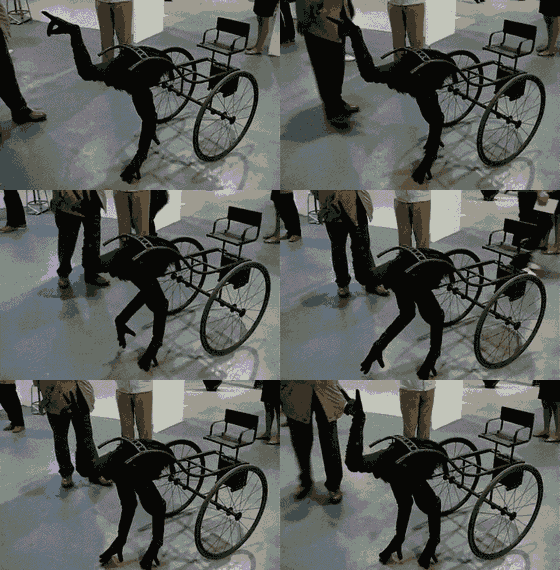
Hand Shaped Ostrich Robot at Kinetica 2012
Recently while cruising the undernet, I ran across this intriguing image of an animatronic bird-thing pulling a small cart. The image is so cool, I thought about trying to duplicate this bot.  Maybe I'd use a hefty 6 volt acid-lead battery to power some micro-controlled stepper motors.


The bird-thing image started me thinking about legged robotics again. What is the best way to pull a load anyway, with bird legs (knees hinged towards the back) or with mammal legs (knees hinged towards the front)? Seems like all real-world pack animals have front facing knees, just like humans do. In fact, it is still common in some parts of the world  for humans to pull loads around with rickshaws. Hum... robotic legs pulling a rickshaw. How about robotic legs strong enough to pull me around in a rickshaw. Strong legs would need a lot of power; generating power adds more weight. Seems like a portable air compressor in a rideable cart and big leg pistons could be a way to go. So once again, what started out as a modesty sized rational project has morphed into a crazy-big-ass-over-engineered circus. I have bravely cleaned out  a 4x8 foot work space in the garage and I'm ready to dive-in. What can I say; this is where my muse is taking me; I can either follow where she leads me or loose my creative way.

Wiki says  the word rickshaw originates from the Japanese word jinrikisha, where jin = human, riki = power and sha = vehicle. From the word jin, I am naming this project Jinny. I am committed now.

This is a big project that may take as long as two years to complete. I will break the project up into three parts:

Cart sketch.
In phase one, I will build a rideable rickshaw that has a portable air compressor hidden under the seat. I have pretty much settled on a design. I already have a 2 hp four-stroke engine (26 lbs) that will drive a Craig's list compressor unit (39 lbs) and I also have a pair of sturdy 14" wheelbarrow wheels. I need to buy a half sheet of  plywood, some 1" thin-walled  electrical conduit, some weldable metal rods and some miscellaneous hardware. The cart will have a foot powered mechanical break system.


Servo follower pneumatic piston.
In phase two, I will build two human sized pneumatic driven legs. My current idea is to use only one pneumatic piston per leg, probably made out of 3" PVC pipe. Thirty PSI would give me 212 pounds of force to use, at a rate of about one stroke per second. The knee joint will be the only actively powered part of the leg mechanism. The piston will be of a servo follower type, where the piston's position mimics the position of a standard servo. This is a design I developed years ago and it is a marvelous actuator solution. I plan to use magnetic angle sensors to monitor the free wheeling upper leg position (hip joint) and to use air pressure sensors to monitor the weight that each foot is supporting. The direction of the leg swing (forward and back) is fixed until changed by the rider (pulling on a set of reins. (Yeehaw!).

Phase three will be writing the arduino uno micro controller program that runs things. This will be the most formidable part of the project, especially since I skipped building a smaller version of the project where I could have developed control loops without accidentally bashing into my wife's parked car. Indeed, the compressor easily produces 100 PSI which could generate over 700 pounds of force at the piston heads. I will have to have several levels of safety built into the design and still be very careful.